When testing metals, the rate at which the specimen is being strained can affect important material properties, and thus affect important results such as offset yield and even tensile strength. Major metals testing standards such as ISO 6892 or ASTM E8 specify certain strain rates at which tests should be run. Pull a metal specimen at a constant rate throughout the test…sounds easy enough right?
In fact, achieving a constant strain rate can be difficult due to system compliance. As a continuously yielding specimen is being pulled in tension, the entire load string (frame, grips, load cell, adapters, etc.) are also deforming due to the typically high load seen in metals testing. Once the specimen yields the stiffness of the load string changes again and since the load plateaus, the deformation of the load string also plateaus. Once this occurs, all of the movement of the frame crosshead is translated into specimen elongation.
It is important for a testing machine to compensate for the changing stiffness seen in the load string throughout a test. If you are interested in learning more about strain control and how it can affect your testing results, please leave a comment below.
Also, please stay tuned to for a video showing a strain control test in accordance to ISO 6892!
Read more
Share your ideas. Tell us your stories. Join the Instron Community.
Welcome to our new Instron Community Blog hosted by Instron. It is a compilation of the freshest, brightest, most-talented minds that Instron has to offer. The world of materials science is so vast and encompasses the broadest range of industries, materials, and challenges that no one person can possibly possess all the knowledge required to be the resident expert – or master of materials science. It takes a small army behind the scenes collaborating and sharing technical know-how, experiences, and ideas to present the most accurate, relevant, and timely information to you – our readers.
We invite you to tell us who you are, share your stories and talk about your experiences. Join the Instron Community.
Monday, December 31, 2012
Friday, December 28, 2012
Why Automatic Extensometry?
When testing the mechanical properties of a specimen, being able to accurately and repeatedly measure the strain the specimen sees is crucial. Many testing standards require that a separate device, commonly known as an Extensometer, be used to ensure the most accurate strain data possible.
So before you run a test, attach a device onto the specimen to measure the strain… that doesn't sound bad, now does it? Now think about having to test hundreds of specimens. Odds are, manually attaching an extensometer to every specimen will add significant time to your testing process. This is where an automatic extensometer should be used.
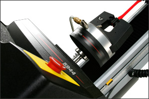
Automatic extensometers allow the user to simply place their specimen into the grips that are being used during the test and hit “start”. You don’t have to worry about attaching the extensometer and removing it once the test is done; it’s done for you! Automatic extensometers can save time, increase repeatability, and reduce operator influence on results. If you are interested in automatic extensometry, check out the AutoX 750. Read more
LABELS:
Accessories,
Biomedical,
Composites,
Metals,
Plastics,
Products,
Quick Tips
Thursday, December 27, 2012
What is R-Value?
R-value (also known as “Plastic Strain Ratio”) is a measurement of the drawability of a sheet metal. Simply put, it measures the resistance of a material to thinning or thickening when put tension or compression. R-value is a very important material property to understand for materials that will be formed into various shapes in their end use. When testing in accordance to popular standards such as ISO 10113 or ASTM E517, R-value is required.
There are two methods to calculate R-value, a manual version and an automatic version. We can assume that the volume of the specimen during the test remains constant to make the calculations easier (see below for details). The manual version of calculating R-value requires that the user measure the initial and final width and length of the specimen using calipers. The automatic method requires the user to measure the axial strain (as opposed to the strain along the thickness of the specimen) and transverse strain to calculate R-value.
The best range over which to calculate R-value is after yield point elongation and before ultimate tensile strength. The benefit of using the automatic method of measuring R-value is that the specimen can be pulled until failure, thus allowing the user to calculate properties such as ultimate tensile strength or strain at break. However, in the manual method, you are to pull the specimen beyond yield-point elongation, but the strain should not exceed the strain at ultimate tensile strength. Once you pull the specimen to this point, you are to unload the specimen to take the final measurements with your caliper.
Since it is difficult to measure the thickness of the material as it is plastically deforming, we can assume that the volume of the specimen remains constant and thus:
Have any questions about plastic strain ratio? Leave a comment below and I'll respond to you soon~
Read more
Wednesday, December 26, 2012
Plastics for Life
The interface between engineering and medicine has been expanding in recent decades - universities are now offering dedicated bio-engineering degrees. One particular application of modern engineering in medicine is the use of polymers as implants in order to aid in the healing process or replace damaged tissue.
Cranial Implants
Head injuries can be life-changing in a way that few other injuries can. Treatment can involve implantation of a skulls prosthesis, which is quite understandably a very delicate procedure requiring the utmost care and attention. However, it is also critical to select appropriate materials, for purposes of production and bio-compatibility. This is where plastics are proving to be extremely useful. In a recent research project, a team of dedicated professionals has created a process for manufacturing bespoke cranial implants with precision, speed and at minimal cost. The patient is taken for an MRI scan and the results are converted by a computer into a 3D model. Using a 3D production method like laser sintering, the implant is then generated. The whole process could take out a great deal of time and complexity involved in the surgical procedure.
Tracheal implants
Similar bio-technology is being used in throat repair. The Trachea is a long tube that connects the lungs to the mouth. When it becomes damaged, it can be very difficult to repair, and implanted materials can cause problems for the patient’s immune system. But using a 3D printed scaffold seeded with the patient’s own stem cells, an implant can be devised that is 100% compatible with the patient’s body. This technology is very transferable into many structures in the body, as the basic manufacturing technique is very flexible and the patient’s own cells are integrated into the implant. The bio-compatibility of the polymer structure ensures that the body integrates the implant, rather than rejecting it
.
However, implantation of any foreign device is a risky procedure, and the doctors and engineers responsible need to be 100% certain of success before engaging in a procedure. Implants should be thoroughly tested on a quality basis in order to prevent deployment of deficient products.
With a combination of Tensile, Compressive, Fatigue and Impact machines (among many others), we have a slew of solutions for a variety of bio-mechanical tests. In particular, we have a well-established history in stent testing and experience with a number of other bio-medical applications. We also have a unique environmental control unit for testing at 37 degrees.
Why not contact us to find out about the testing capabilities that we can offer? Read more
LABELS:
Featured Posts,
Plastics
Tuesday, December 18, 2012
Happy Holidays
To share a little holiday cheer, I've worked with some of our blog authors (aka application specialists) to put together a fun montage of testing various types of holiday materials from wrapping paper to ornaments to garland ....
Enjoy and happy holidays!
Read more
Enjoy and happy holidays!
LABELS:
Featured Posts,
We Test That
Monday, December 17, 2012
Bluehill Updates
Parasar Kodati, our Bluehill® Product Manager, wrote an exciting post on our Bluehill blog about new updates to the software, as well as announces a new product that makes managing and analyzing results so much easier.
Check it out~ Read more
LABELS:
Featured Posts,
Software
Thursday, December 13, 2012
Question from a Customer
Q. What is the difference between percentage of full-scale and percentage of reading?
A. The accuracy of a device describes how close a measurement is to the actual value. It is usually presented in one of two forms: percentage of full-scale or percentage of reading.
Percentage of full-scale, usually shown as %FS, is a fixed error, and therefore, has a greater influence at lower measurement values. For example, if a load cell has a 200 lbf capacity and an accuracy of 0.3%FS, the error is 0.6 lbf throughout the measurement range. Therefore, at a measurement of 20 lbf, the 0.6 lbf error is 3% of the reading. This is outside of the ASTM E4 requirement that measurements should be within 1% of reading.
Percentage of reading is usually shown as %RO. For example, if a load cell has a 200 lbf capacity and an accuracy of 1% RO, then at a measurement of 20 lbf the error is 0.2 lbf or 1% of the reading, and within ASTM E4 requirements. Devices that specify accuracy as a percentage of reading typically have a wider range of use, since this is a more difficult specification to meet. Read more
LABELS:
FAQs,
Featured Posts
Balancing the Load Cell
We are often asked how frequently an operator should balance the load cell during testing. Many lab managers require the operator to balance a load cell before the start of a new sample; others require balancing the load cell before testing every specimen. We believe that either procedure is acceptable, as long as you follow one major rule:
If you notice a change on the load channel display after gripping, you can remove the load using automated software features such as preload or specimen protect, or by manually adjust the position of the crosshead. Read more
Never balance the load cell when there is a specimen clamped in both grips
Instron load cells can detect a change in load as a result of simply gripping the specimen. If the load is balanced after a specimen is gripped, you risk zeroing out a real load. This real load will be subtracted from or added to reported results, thereby falsely increasing or decreasing actual values depending on whether or not there was a compressive or tensile load on the specimen before the load cell was balanced.
If you notice a change on the load channel display after gripping, you can remove the load using automated software features such as preload or specimen protect, or by manually adjust the position of the crosshead. Read more
LABELS:
Featured Posts,
Quick Tips
Measurement Uncertainty in Calibration
Instron’s reputation depends upon the quality of its products, the accuracy of its measuring devices, such as load cells and extensometers, and its services to regularly verify that those devices are performing to a required standard. For many years, the tag line “The Difference is Measurable” has shown our commitment to this accuracy. But how do we show it in practice?
No measurement can be said to be completely accurate. There is always some degree of doubt about the result of a measurement. For example, there may be some degree of inaccuracy in the measuring device itself or there may be differences in how people perform or read a measurement. That doubt is called the uncertainty of the measurement.
In short, any measurement result is only complete when a statement of the uncertainty in the measurement accompanies it. When the uncertainty in a measurement is evaluated and stated, you can properly evaluate the quality of the measurement.
There are many different accreditation organizations worldwide, and several in the USA. To ensure that the different accreditation organizations harmonize their standards and processes so that they can accept each other's accreditations internationally, the International Laboratory Accreditation Cooperative (ILAC) was established and has now more than 70 accreditation bodies worldwide as signatories to their Mutual Recognition Arrangement (ILAC-MRA).
In 2010, ILAC published the ILAC Policy for Uncertainty in Calibration to harmonize the expression of uncertainty of measurement on calibration certificates and on scopes of accreditation of calibration laboratories. One of the major requirements of this policy is that each calibration verification
measurement should be accompanied by the associated uncertainty measurement.
Take a look at your last calibration certificate. If you have a certificate issued from another calibration laboratory, you may see only a general statement relating to uncertainty of measurement. However, if the Instron Calibration Laboratory has issued your certificate, you will see that each individual result is accompanied by an uncertainty measurement that has been calculated with that result.
Instron has long considered the reporting of uncertainty of measurement to be good metrological practice and has been reporting measurement uncertainties that are consistent with the new ILAC requirements for many years. Instron’s commitment to offering quality products and services shows in many ways. The accurate reporting of measurement uncertainty with every calibration result is one more reason why we say:
The Difference is Measurable. Read more
A measurement offers a quantitative value to a property of an item. How heavy is it? How long is it? How hot is it?
No measurement can be said to be completely accurate. There is always some degree of doubt about the result of a measurement. For example, there may be some degree of inaccuracy in the measuring device itself or there may be differences in how people perform or read a measurement. That doubt is called the uncertainty of the measurement.
Good practices, such as regular maintenance and traceable calibrations, careful calculations, regular training, and accurate and consistent record keeping all help to maintain system performance and increase measurement accuracy. However, to properly judge the quality of any measurement, we need to quantify and report the uncertainty associated with that measurement.
We need to know two things: the width, or interval, of the margin of uncertainty, and how confident we are that the true value is within that margin. For example, we might say that the gauge length of a specimen measures 25 mm, having an uncertainty of measurement of 0.11 mm with a 95% confidence level. This
means that we are 95% sure that the gauge length is between 24.89 mm and 25.11 mm. The uncertainty statement is an indication of the quality of the measurement.
In short, any measurement result is only complete when a statement of the uncertainty in the measurement accompanies it. When the uncertainty in a measurement is evaluated and stated, you can properly evaluate the quality of the measurement.
Instron’s calibration standards and processes in North America and Asia are accredited by the National Voluntary Laboratory Accreditation Program (NVLAP). NVLAP is a program administered by the National Institute of Standards and Technology (NIST), the National Metrology Institute (NMI) of the United States. NVLAP regularly assesses Instron’s competence in performing accurate calibration and verification processes including the accuracy of the equipment used in those processes.
In 2010, ILAC published the ILAC Policy for Uncertainty in Calibration to harmonize the expression of uncertainty of measurement on calibration certificates and on scopes of accreditation of calibration laboratories. One of the major requirements of this policy is that each calibration verification
measurement should be accompanied by the associated uncertainty measurement.
Take a look at your last calibration certificate. If you have a certificate issued from another calibration laboratory, you may see only a general statement relating to uncertainty of measurement. However, if the Instron Calibration Laboratory has issued your certificate, you will see that each individual result is accompanied by an uncertainty measurement that has been calculated with that result.
Instron has long considered the reporting of uncertainty of measurement to be good metrological practice and has been reporting measurement uncertainties that are consistent with the new ILAC requirements for many years. Instron’s commitment to offering quality products and services shows in many ways. The accurate reporting of measurement uncertainty with every calibration result is one more reason why we say:
The Difference is Measurable. Read more
LABELS:
Featured Posts,
Service and Support
Wednesday, December 12, 2012
Grip Penetration Effects
How To Determine Effective Gauge Length
If gripping pressure on the clamped specimen is not uniform throughout the clamped area, a certain amount of specimen extension may take place within the grips. When this happens, if the elongation is measured from the test curve and a calculation of precentage elongation is based on the separation between the grip at the start of the test, the resulting figure will be in error.
Extension of the specimen within the grips is referred to as "grip penetration". It may not be apparent from examining the load elongation curve whether grip penetration has occurred since it will not produce a stick-slip effect, but it is proportional to the applied load. As grip penetration is proportional to load, the load elongation curve will remain smooth and apparently normal.
A method for determininng the presence and magnitude of possible grip penetration is to plot elongation against gauge length for a given force (Fx). If the resulting line, when extrapolated to zero gauge length, does not pass through the origin, but gives a positive displacement on the elongation axis, then this is the restult of grip penetration. It is essential when performing these tests to always test the specimen at the same strain-rate since certain materials are strain-rate sensitive. For example, the longer the gauge length, the faster the required crosshead speed, and the ratio between the gauge length and the crosshead speed will be constant.
Calculating Effective Gauge Length
The intercept gives a value (Ej) representing elongation within the grip at a specified load. The quantity AE represents the true elongation for a corresponding gauge length or grip separation. When calculating elongation from a load versus strain graph, the value Ej should be subtracted from the total elongation before dividing this value by the gauge length or grip separation figure. Read more
LABELS:
Featured Posts,
Quick Tips
Tuesday, December 11, 2012
Looking After Your Grips
Any successful gripping solution can be adversely affected by poor maintenance. Many common gripping techniques rely on friction or local surface deformation of the specimen to function. If the gripping surfaces become worn or contaminated, a loss in gripping efficiency occurs. Ultimately, this causes the specimen to slip, leading to an invalid test.
The first response to slippage is often to increase the gripping force by over-tightening the mechanical grips or to increase the pressure of pneumatic or hydraulic grips. Although this may temporarily solve the slippage, it can also bring new problems:
Here are some golden rules for reliable gripping:
The first response to slippage is often to increase the gripping force by over-tightening the mechanical grips or to increase the pressure of pneumatic or hydraulic grips. Although this may temporarily solve the slippage, it can also bring new problems:
- Simple screw action grips are often tightened with a spanner or wrench. It's very easy to exert high torque loadings to the load cell unless care is taken. Excessive tightening can easily damage low force load cells. Taken to extremes, it's possible to damage the grips themselves. Using a small torque wrench will allow you to achieve consistent gripping force.
- Increasing the pressure applied to the specimen by the gripping system can also increase the chances of influencing the mechanical properties. This is especially true of materials that are weaker in compression than in tension. We find that increases in jaw breaks often accompany increases in the gripping force.
Here are some golden rules for reliable gripping:
- Regularly clean and lubricate moving parts with the correct grades of lubricant as advised by the manufacturer. This is especially important for wedge action grips, which rely on the smooth sliding of the jaw faces along an inclined plane for their correct function.
- Periodically inspect the grips for defects, such as cracks or leaks in hoses.
- Periodically verify that the pressure gauges are accurately registering air or oil pressure to the gripping system.
- Replace jaw faces when the surfaces become worn, damaged, or contaminated. Some jaw faces, such as rubber-coated types, can degrade over time simply due to exposure to air and light. This degradation can accelerate if the jaw faces are used under non-ambient conditions in an environmental chamber.
- Do not use more gripping force than necessary to provide reliable, slip-free gripping.
- Old grips don't necessarily work with new materials or specimens. You may find that special grips or different jaw face surfaces are needed. You can try a variety of things to modify existing gripping methods including emery cloths, sticky tape, etc.
LABELS:
Accessories,
Featured Posts,
Quick Tips
Thursday, December 6, 2012
Trends In Hardness Testing
Recently, Bill O'Neill - Director of Business Development and Sales for Hardness Americas - wrote an article for inclusion in Quality Magazine. Focusing on various methods to improve productivity, accuracy, and efficiency, we've included a short insert below.
Consistent with the unprecedented advancing technology we all benefit from in just about anything related to computers, communication, digital vision, and hardware engineering, hardness testing has rapidly evolved in technique—more so in the past 20 years than any previous developments since the inception of this important materials test method. Limitations in regards to material geometry, surface finish, productivity, efficiency, data manipulation, and results reporting have been mitigated while continually undergoing enhancement. The result is increased ability and dependence on “letting the instrument do the work,” contributing to substantial increases in throughput and consistency, while freeing up the advanced operator for other responsibilities or allowing less experienced operators to handle hardness data acquisition. With the myriad of fully integrated systems now available, the labor intensive, subjective and error-prone processes of the past are virtually eliminated. More sophisticated, accurate and productive processes can quickly, reliably, and with extreme precision provide useful, material critical information.
Materials testing, including hardness testing, are useful processes for analyzing component properties and can be accomplished through a multitude of methods and techniques. Determining material hardness can provide valuable insight into the performance, durability, strength, flexibility, and capabilities of a variety of component types — raw materials to carefully prepared specimens to finished goods. In today’s extremely competitive global market, with high expectations on accuracy and productivity, quality and productivity errors have serious consequences. Manufacturing, research, and quality control now more than ever must depend heavily on new and evolving techniques to revolutionize more traditional processes if they want to maintain a competitive pace.
You can find the entire article here. Read more
LABELS:
Featured Posts
Wednesday, December 5, 2012
Making Bricks
With Christmas fast approaching, many parents minds will be turning to toys for their children. The market is pretty cramped these days, but I'm particularly fond of an old household favourite: Legos. It feels like you can make anything from Legos now, with kits allowing the 'child' to build anything from municipal buildings to starships. But how are the bricks themselves made? How is the same excellent level of quality assured in every single brick?
The answer involves Injection Moulding; a commonly used technology for high quality, high demand products. Injection moulding uses plastic granules which are heated together into a thick ‘melt’. The melt is then forced under enormous pressure into finely detailed moulds, ensuring a supreme degree of accuracy.
But putting together an injection moulding process is no mean feat. One of the principal challenges of process design is matching the machinery with the raw material. Knowledge of the flow characteristics and thermal conductivity of the melt are invaluable in preventing poor mould filling and defects, which are both linked to poor product quality. In short, the mould designer needs to know how viscous, or thick, the material is and how quickly it cools. Once the process is designed and optimised, tests can be performed to ensure that incoming raw materials are of the appropriate quality.
The plastic used in Lego is known as Acrylonitrile Butadiene Styrene, or ABS for short, and has excellent mechanical properties. For simulating the injection moulding of ABS, or many other plastics besides, the SmartRheo range of Capillary Rheometer systems can be used. The machinery is adaptable and can readily be converted to perform rheology (flow), pvT (pressure, volume and temperature) or thermal conductivity testing as needs arise.
Just to finish, I’m going to leave you with some awe-inspiring Lego projects from around the internet!
Jet Turbine model
A REALLY tall tower
Chess board
Two-storey house
Custom printer Read more
LABELS:
Featured Posts,
Plastics
Tuesday, December 4, 2012
Are Materials Testing Systems Potentially Hazardous?
They certainly can be. Material testing involves inherent hazards from high forces, rapid motions, and stored energy. You must be aware of all moving and operating components that are potentially hazardous, particularly the actuator in a servohydraulic testing system or the moving crosshead in an electromechanical testing system.
Whenever you consider that safety is compromised, press the Emergency Stop button. This will stop the test and isolate the testing system from hydraulic or electrical power.
Ensure that the test set up and the actual test you will be using on materials, assemblies or structures constitute no hazard to yourself or others. Make full use of all mechanical and electronic limits features. These are supplied to enable you to prevent movement of the actuator piston or the moving crosshead beyond the desired region of operation.
Your best safety precautions are to gain a thorough understanding of the equipment you are using by reading the instruction manuals, to always use good judgment, and to observe all Warnings and Cautions. You will find more specific warnings and cautions in the manuals whenever a potential hazard exists. Read more
LABELS:
Featured Posts,
Quick Tips
Subscribe to:
Posts (Atom)