Welcome to our new Instron Community Blog hosted by Instron. It is a compilation of the freshest, brightest, most-talented minds that Instron has to offer. The world of materials science is so vast and encompasses the broadest range of industries, materials, and challenges that no one person can possibly possess all the knowledge required to be the resident expert – or master of materials science. It takes a small army behind the scenes collaborating and sharing technical know-how, experiences, and ideas to present the most accurate, relevant, and timely information to you – our readers.

We invite you to tell us who you are, share your stories and talk about your experiences. Join the Instron Community.
Showing posts with label Featured Posts. Show all posts

Friday, December 12, 2014

Challenges in Composites Testing Masterclass


On 2nd December, Instron had the great pleasure of hosting a composites-focused masterclass for customers, based at our European Headquarters in High Wycombe, England.

Focused around a combination of seminars and active workshops, our customers were involved in discussions surrounding a wide variety of composites-based testing challenges, from the importance of specimen alignment, to dynamic testing and advanced measurements, as well as productivity of testing and strain measurement.


We were also pleased to host Nigel O’Dea (Founder and Director of OB2B Industrial Marketing & PR) who brought with him 25 years of industry experience. His involvement and presentation reinforced the importance of the global strategic growth and challenges faced within the composites industry.


At the end of the masterclass, all customers were invited to stay on for a sneak peek around the newly vamped factory floor and had the opportunity to get hands on with a variety of demonstration machines hosted in our Applications Lab.

Overall, the masterclass proved to be an insightful look into the challenges of composites testing, and also an opportunity for great discussion between customers and our dedicated applications specialists. Here’s what one of our customers had to say about the day:

“Very well run event, all the speakers were very approachable. It totally reinforced the message that Instron is a key partner for materials testing and able to share helpful, up-to-date knowledge and insight, not just a test machine supplier.”

We will be running similar events throughout 2015; so, look out for new dates being confirmed on our website.


Read more

Friday, November 21, 2014

Helping to Standardize High-Rate Testing of Composites


Instron has joined a new international group that is seeking to develop a best practice guide and test standards specifically for testing composites at high-strain rates.

As the automotive industry seeks ever-more-urgently to embrace composites, there is an increasing demand for testing composite material behavior at high-strain rates. The need for detailed data to inform crash simulation models first drove a renewed demand for equipment over the last 3 years, and now there is a need for international standardization in methodologies and data handling. The group’s aim is to facilitate generation and exchange of reliable and comparable test data in this highly challenging area.

The working group has been coordinated by the University of Dayton Research Institute, and currently composes about 20 organizations including major automotive manufacturers, composite materials producers, test houses, and research institutes. As a world leader in high-rate servohydraulic testing systems, the dynamic systems team at Instron are very pleased to share their expertise with this initiative that will make a tangible difference to the industry. Similarly, Instron CEAST will be contributing to work on drop-weight based techniques for high rate testing.

The working group is looking for more European contributors especially, but we would strongly encourage all our customers with expertise in this area to join us in supporting the project. Please feel free to contact Instron applications specialist, Dr. Peter Bailey, if you would like to know more.

Read more

Wednesday, November 5, 2014

Challenges of Rigorous Demands


The world of materials testing is changing …
  • materials are getting stronger, stiffer, and lighter 
  • test standards are becoming stricter 
  • testing labs are asked to perform more complex analytical tests
With all of these changes affecting the way labs test, it’s important to think about the following questions: How does your lab environment challenge test results? Is your lab equipped to handle the new strength of specimens? Are you testing under load or position control parameters, or do you require the use of strain control?

These questions, when coupled with the changes above, are all factors we have discussed with our customers and are sharing with you.

Challenge #1

AVE 2 Carbon Fiber LaminatesThe automotive and aerospace industries are growing and demanding that materials become stiffer, stronger, and lighter. This new breed of materials is helping the industry produce lighter and stronger products, but lab operators are finding that the large energy release may damage contacting extensometers. To reduce the cost of maintenance for labs testing these challenging materials, video extensometers are an ideal  solution – they don’t contact the material, and therefore, they are unaffected by the high-energy breaks of materials, such as carbon fiber composites or rebar.

Challenge #2

With the growing demands come newer standards that place stricter requirements on the type of extensometer you are allowed to use. For example, ISO 527-2012 now requires that devices have an accuracy of just 1 micron in order to measure the modulus of the material. 1 micron is exceptionally small (about 100 times smaller than the width of the average human hair) and is exceedingly difficult to measure. Although this accuracy can be attained with some traditional clip-on extensometers, clip-ons have limited travel and typically can’t measure strain through failure for ductile specimens. In addition, they may cause premature failure due to stress risers from knife edge contact.

Until recently, there hasn't been a video device that could meet the new standard requirement due to problems with lighting and air flow that naturally occurs within a lab, which ultimately affects the device’s ability to provide accurate results.

To prevent the lab lighting from making a difference, we have incorporated a patented lighting system into our new video extensometer that floods the specimen with polarized light and use a polarized filter on the lens. This enables the video extensometer to produce consistent results no matter the lighting conditions, including flicker from fluorescent lights or the difference in lighting from a lab window.

Secondly, all video systems are affected by air flows in the room from sources like air ducts and heat sources. These air flows are similar to what you may see on asphalt on a hot day. The air currents and heat sources in your lab are probably much smaller, but since 1 micron is so small even minor perturbations make the measurement impossible. Our engineers incorporated a patented system of fans into the video extensometer to prevent these air flows between the specimen and the camera, enabling the test to yield accurate results whether your air system is off or running at full speed.

Challenge #3

AVE 2 Metals SpecimenNew standards are also placing requirements on the way that tests are being controlled. In the past, most – if not all – tests were run under load or position control parameters, but newer standards may prefer or require the use of strain control. This can be done with contacting extensometers, while pre-existing video extensometers struggle to run strain control tests because the images taken have to be processed by the computer and then sent to the software to adjust the frame movement accordingly. There is a large delay between the images being taken and the processing by the computer, which means that by the time the frame reacts to the strain measurement the value has changed.


To resolve this, the new video extensometer now measures strain at the camera in real time and then sends the data directly to your test frame. This drastically reduces the response time of the camera and allows for clean strain control.

Challenge #4

Extensometers are excellent for materials testing, but only give you a point-to-point measurement. Other measurement techniques, such as digital image correlation, can give you more information about material behavior during a mechanical test, but they typically require expensive and complicated equipment and software. Because of the high barrier to entry, only a few labs take advantage of this technology and are able to make key insights about their material behavior that other labs can’t.

Instron has lowered the barrier to entry for digital image correlation by offering our video extensometers along with dedicated digital image correlation software. The extensometer images are automatically synchronized in time to the data from the load frame, which means that you can now run a test and begin producing full field strain maps in less than one minute.
Read more

Wednesday, June 25, 2014

Composites on the Move

Composites are now a broad and well-established family of materials, but industry press releases frequently discuss “new and exciting” developments and opportunities. It should be remembered that there has been a commercial market in high performance, structural composites for well over 30 years, and European automotive manufacturers have made considerable use of lower performance glass fiber reinforced polyester (GFRP) bodywork since the 1950s.

Thermal image showing heating at failure
of a static tensile test (1mm/min)
of an impacted composite specimen
Furthermore, a high level of interest from the aerospace industry has resulted in a wide range of well-established static test methods giving reliable results. Sadly, there is still only limited consensus, so test houses and machine manufacturers find themselves maintaining an extensive catalog of fixtures in order to meet diverse international and industry standards. From this starting point, it might be argued that there is little news in composites testing, but in fact some exciting trends have started to develop.

Recently published in AM&P magazine, Peter Bailey, PhD - Sr. Applications Specialist - wrote an article on the growth in the dynamic testing market for composites.

We are including it here for you to download.
Read more

Backward Strain at Yield — Discontinuous Yielding / YPE Material

During a recent customer visit, a concern was raised about a turnaround point on the graph that they had not previously seen. Following a bit of investigation, the customer was producing galvanized steel of various grades, some of which was aged. The graph below shows a magnified view of the fairly aggressive upper yield point (UYS or ReH), which results in an almost immediate drop in stress.
 
The customer had been testing galvanized steel for many years and had never seen negative strain at the yield point before. The new system, which was running Bluehill® 3 with an AutoX, showed backward strain during yield, which proved surprising to the customer as it was not present in historical data. The AutoX was able to more accurately plot the reduction in strain (9 µm of movement) at yield due to its increased accuracy over the previous system.
 

The negative strain after upper yield is based on the way metals yield within a parallel section of material. Stress concentrations form at the shoulders or at the jaw faces in parallel specimens and typically propagate through the material at 45° angles. As the initial yielding takes place outside of the gauge length, which causes the stress (load) to drop, the gauge length contracts and a reduction of strain is seen on the graph. The video shows how the dislocations travel through the material, in this case from the bottom to the top of the specimen (12—24 seconds).

The diagram below shows how the extensometer arms are unable to see all of this extension.
 
 
To verify that the machine was operating correctly and the backward strain was a material characteristic, we used both larger and much smaller gauge lengths. The parallel length of the specimen was 65 mm, so a 60 mm and 10 mm gauge length was chosen for comparison. We found that when the 60 mm gauge length was used, no negative strain was observed. However, when the 10 mm gauge length was used, the negative strain dramatically increased in percentage.
Read more

Friday, June 13, 2014

Webinar Archive Hosts Recordings


Instron live webinars provide the opportunity to hear updates from experts on industry news and testing techniques. If you happen to miss the webinars, our library hosts the recordings:

http://www.instron.com/wa/landing/default.aspx?land=6537db54059&MPID=5740

Check back to watch the archive grow.
Read more

Thursday, April 17, 2014

The Truth About Strain Gauge Load Cells vs. Pressure Transducers


Load cells independently and directly measure the force being applied to specimens. Pressure transducers measure force indirectly from the oil pressure observed in the cylinder. Which is superior? The answer is simple: Load cell technology due to the fact that some of the pressure in a hydraulic system has nothing to do with the load being applied to the specimen.


Design Differences: Left Load cell measures force directly | Right Pressure Transducer measures force indirectly

For instance, moving the cylinder requires some hydraulic pressure to overcome the friction between the piston and cylinder; raising the piston off the cylinder bottom can require a significant amount of pressure; and the weight of the oil itself creates pressure in the system. This pressure creates errors in the indication of load and can raise the lowest calibrated reading (sometimes as high as 10% of capacity). Machines using pressure transducers attempt to eliminate these inherent load measuring errors:
  • Systems are designed without seals ... Since piston seals cannot be used on pressure transducer systems because of the frictional forces that would result, hydraulic fluid spills out of the top of the cylinder. Extra drain lines are needed to return the fluid to the reservoir. Over time the overflow can increase as the piston and cylinder assembly wear resulting in decreased testing speeds
  • Additional plumbing and fittings are needed to eliminate friction ... Hydraulic bearing pressure and return lines are used to float the piston. Meant to keep the piston from touching the cylinder sides to eliminate friction, it requires more parts, more mechanical adjustments and could possible limit the machines ability to handle off-center loading.
  • Electrical pressure offset is required for the weight of the oil in the cylinder ... The pressure reading is affected by the weight of the column of oil. As the piston is raised, the volume and height of oil in the cylinder changes requiring a complex chain and pot assembly to electrically offset the weight of the oil as the piston is moved. Accuracy of the load readings over the entire stroke of the machine is questionable.
When making critical business, design, or process decisions based on the mechanical properties of a material, shouldn’t these properties be measured directly with a load cell rather than indirectly with a pressure transducer?

Download the white paper
Read more

Thermoset and Thermoplastic Composites ... What’s the Difference?

As composites continue to be adopted in more industries, fiber-reinforced plastics can be found in products that people interact with every day, including cars and sporting goods. Fiber-reinforced plastics consist of reinforcing fibers surrounded by a plastic matrix. There are several types of fibers that can be used including glass, carbon fiber, and aramid which give the material its high tensile strength. The matrix gives the composite the compressive strength and, in the case of fiber reinforced plastics, can be made using thermoset or thermoplastic polymers.

Thermoset polymers are polymers that are cured into a solid form and cannot be returned to their original uncured form. Composites made with thermoset matrices are strong and have very good fatigue strength. They are extremely brittle and have low impact-toughness making. They are commonly used for high-heat applications because the thermoset matrix doesn’t melt like thermoplastics. Thermoset composites are generally cheaper and easier to produce because the liquid resin is very easy to work with. Thermoset composites are very difficult to recycle because the thermoset cannot be remolded or reshaped; only the reinforcing fiber used can be reclaimed.

Thermoplastic polymers are polymers that can be molded, melted, and remolded without altering its physical properties. Thermoplastic matrix composites are tougher and less brittle than thermosets, with very good impact resistance and damage tolerance. Since the matrix can be melted the composite materials are easier to repair and can be remolded and recycled easily. Thermoplastic composites are less dense than thermosets making them a viable alternative for weight critical applications. The thermoplastic composites manufacturing process is more energy intensive due to the high temperatures and pressures needed to melt the plastic and impregnate fibers with the matrix. The energy required makes thermoplastic composites more costly than thermosets.

These two similar materials have such different properties that both will continue to be used in different applications for very different reasons and the products of the future will likely be a combination of both.
Read more

Friday, April 11, 2014

Testing United States Bridges at Columbia University


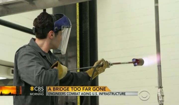
With recent events causing concern about the stability of major bridges, the Department of Civil Engineering and Engineering Mechanics at Columbia University is evaluating their durability with the help of Instron. Click to watch the video:

 A Bridge Too Far Gone

The Robert A. W. Carleton Strength of Materials Lab discusses with CBS News how they are testing timeworn infrastructure in the United States to understand how they may react to various scenarios.
Read more

Monday, December 30, 2013

Instron Year in Review

We've created a Year in Review to highlight exciting moments of 2013. We want to keep you up to date on all aspects of Instron® – from our community relations to our acquisitions to available webinars, and new products. There was never a dull moment or a period of time when we weren’t aiming to meet the expectations and needs of our customers.

Every experience you have with Instron is invaluable to us as a company. Specifically within TechNotes, I work with our application engineers and product managers to bring you the most relevant and industry-specific news that will assist with your testing applications. Instron professionals are some of the best in the industry and hold seats on many of the ASTM and ISO committees. It’s my goal to share with you their knowledge and experience in order to better support your testing applications. So keep the feedback and questions coming! I welcome any chance I have to speak with you on ways to better communicate just exactly what you’d like to hear.

Thank you for your continued support as we move forward into 2014 and I look forward to future communications with you!


Best regards,

Denise Czerpak
TechNotes Editor
Download Now: A Year in Review
Read more

Monday, October 28, 2013

Calling all Hockey Players: How Safe & Durable is Your Equipment?

Imagine being struck by a hockey puck traveling 100+ MPH while on the ice. As is the daily grind of hockey players everywhere, they rely heavily on the gear they choose to protect their bodies.

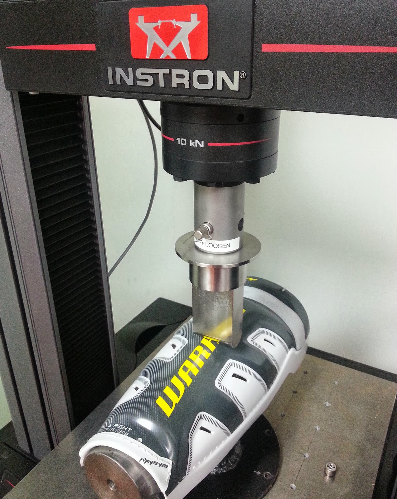
“We are seeing a trend in hockey equipment today that focuses on equipment being lightweight,” explains Olivier Jajko, Product Engineer at Warrior Sports, a leading global sporting goods manufacturer. “What customers may not know is that in order to reduce the overall weight of the equipment, some manufacturers are reducing the amount of material used."

Ultimately, that means less coverage for the player. This trend – this focus on the removal of equipment parts to make it lighter – is something Warrior does not take part in. In fact, they focus their experience and knowledge on developing smarter, more intelligent materials. “It’s important that we quantify the material stiffness and maximum loads that our products can withstand. We strive to keep the weight of the equipment down, but are not willing to sacrifice the protection of the players,” says Jajko. During the new product development cycle, Warrior tests the materials to determine stiffness, as well as strength at failure. This helps ensure that the right materials are selected and the players are securely protected. Once the finished product is created, the design and finished component must be re-evaluated.

In addition to following this trend of product development, Warrior Sports is also maximizing product safety. They recently developed a two-way protective padding – SmartCap – which is the first of its kind. The patent-pending padding not only protects the players from bumps and hits during a game, but also protects the opponent during contact. This type of innovative design is helping to make hockey a safer sport without entirely changing the nature of the game.
Read more

Friday, June 14, 2013

A New Long-Term Bypass Solution


Today, heart disease is so common that it’s a fair statement to make that you or someone you know has been affected by this illness. It’s estimated that more than 17 million people around the world lose their lives to heart disease every year, according to the World Health Organization. And in the US alone, more than 500,000 of those patients undergo bypass surgery. Most surgeons will “borrow” blood vessels from another part of the patient, such as the mammary artery or saphenous vein; another option is to use a prosthetic graft material. Tissue Engineering will soon provide the superior option, replacement parts made from the patient’s own cells.

While prosthetic and “borrowing” the patient’s veins are popular and familiar choices amongst bypass patients, there is risk involved. The prosthetic grafts have the chance of rejection by the body because they are not natural and are foreign to the body.  Also, the plastic material has been shown to increasing clotting and/or become infected, resulting in additional hospitalization. Using existing veins/arteries is limiting as the supply is not endless, as many as 40% of bypass patients are unable to choose this option due to disease or previous use.

Tissue engineering  – a process that makes replacement blood vessels, in vitro, a reality – allows for a long-term solution for bypass patients. A patient’s cells are grown on a 3D scaffold, which could be natural or a manufactured material, in an environment that is similar to the body. The resulting tissue is then implanted in the patient. With tissue engineered parts, you are not “borrowing” from other areas of your body reducing the concern about availability and because the concern for rejection is obsolete, because the patient’s body recognizes the cells as its own.

To be successful, tissue engineered implants must be both biologically and mechanically similar to native tissue.  This means that the scaffold material and the end products are tested and characterized using tension, compression, and other forces to make sure that they can endure the physical strains of implantation.  Research has also shown that growing tissues under these same mechanical forces (exercising the tissue) results in a tissue similar to native tissue.

In addition to heart disease treatment, tissue engineering has the ability to change modern medicine in many different areas.  Pediatrics is a special case.  Current mechanical medical devices are able to “cure” pediatric disease and defects; however because the patients are babies and their bodies are growing quickly, the surgery must be repeated many times to correct the size of the device.  Tissue engineering offers a solution that can grow with the patient and minimize the number of invasive surgeries necessary.
Read more

Google for Test Results


There are many situations where we need to analyze test results, not just from one sample file, but results that are spread across different sample files that were tested at different times with slight differences in setup or calculations. Are you ever in a situation where you would like to have all the relevant data together without spending a lot of time going through multiple files and copy-pasting the results? The answer to this lies in storing your results in a database. Unlike a file-based system, database storage is optimized for search and retrieval of information. It allows you to quickly narrow down to the right data set within seconds and it saves your search criteria for future use. This decreases the amount of time lab operators spend on moving and organizing data, while increasing the productivity and throughput of the lab.


Earlier this month, Parasar Kodati, Software Product Manager, hosted a live database management webinar. If you missed the opportunity to see it live, you can now take advantage of watching the webinar at your convenience.
Read more

Question from a Customer


Q: Do you have the necessary equipment and expertise to adjust and verify Instron equipment to accuracy levels demanded by national and international standards such as ISO and ASTM? Do your verification/calibration certificates report measurement uncertainty for each measurement taken?

A: Our verification certificates report calculated measurement uncertainty for each measurement taken and are in compliance with the International Laboratory Accreditation Cooperative (ILAC) Policy for Uncertainty in Calibration. Instron Service personnel are factory trained to setup Instron equipment to meet and exceed these standards.

It should be noted that most Instron equipment can operate to specifications that exceed international standards. Our staff is equipped with calibration standards having the low uncertainties of measurement required to verify performance of Instron systems beyond levels found in many international standards. Many calibration suppliers do not have standards with the accuracy required to verify to these levels. For example: Instron maintains a primary force standard that is transferred to our deployed working standards – the need for a secondary standard is eliminated, the “chain of calibration” shortened, and measurement uncertainty is reduced.


Read more

Friday, February 15, 2013

Question from a Customer: Why is strain rate important?

A. Strain rate is the speed at which a material is deformed and different strain rates can have a big effect on the tensile properties of some materials.
Take silly putty as an example. If you slowly pull on a piece of silly putty, it will stretch an enormous amount before it breaks. But if you pull on it quickly, it breaks almost immediately. This is known as strain-rate sensitivity. Many plastics and polymers and some steels are strain-rate sensitive.
So it’s important to remember that stress/strain data captured at lower strain rates may not produce accurate predictions for the properties of that material at high strain rates. Using that data to analyze and design parts and structures can result in those parts and structures being perfectly able to withstand predicted day-to-day forces. However, when subject to sudden high strain rates such as those found in a collision, those parts and structures could shatter rather than absorb the energy of that collision.

For more information on various materials testing terminology, visit our online glossary.
Read more

Reminder: Don't Let Your Standards Slip

You most likely understand the importance of regularly calibrating your testing and measuring equipment and making sure it is maintained to the highest standards to ensure the data that you capture is as accurate as possible. But do you regularly review your testing standards?

ASTM and other standards are continuously improved and amended. Email notification of changes and update subscription services can help you make sure that you stay current. However, it’s important to occasionally review the standards that you work with and examine your test methods and testing practices and procedures against those standards. Particularly for those signing their name to a test report or certification, it's important to question the assumptions and methods used to obtain results and to make sure that you are still fully meeting the standard’s requirements.
Read more

Materials in Space

Launched in 1998, the International Space Station is a research laboratory that enables the study of many scientific disciplines under the unique conditions of the space environment. The station is a shared project between five space agencies: the National Aeronautics and Space Administration (USA) (NASA), the Russian Federal Space Agency (Roscosmos), the Japan Aerospace Exploration Agency (JAXA), the European Space agency (ESA), and the Canadian Space Agency (CSA).
Among the many scientific disciplines studied is, of course, materials science.

Space offers scientists a unique environment in which to examine their field of interest. The orbiting space station offers a very low gravity, or microgravity, work domain. Moreover, the rarified atmosphere of the low earth orbit presents unusual conditions that are not encountered on earth.

For the materials scientist, there are two main aims:
  • Expose materials and components made on earth to the conditions of the space environment and then test them to identify changes resulting from that exposure.
  • Test materials that are formed or processed in space to compare them with the same materials similarly formed or processed on earth.
Material Exposure
The space environment is surprisingly harsh. Atomic oxygen (O1), a free radical, is prevalent in the atmosphere of the low earth orbit and is highly corrosive to many polymers and some metals. Ultraviolet radiation deteriorates many polymers and thin film coatings. The vacuum in space can also alter the properties of many materials and the operation of components. Impacts from dust, meteoroids, solar wind particles, and man-made debris can, of course, damage materials and components.
To investigate the long-term effects of the space environment on materials is the aim of MISSE - the Materials International Space Station Experiment. MISSE evaluates the performance, stability, and long-term survivability of materials and components (switches, mirrors, and so on) for NASA, the Department of Defense (DOD), and commercial companies that have interests in space missions, both in earth’s orbit and beyond.
The materials and components to be tested are packed into Passive Experiment Containers (PECs). These containers, the size of a small suitcase, are secured to rails on the outside of the space station during an astronaut’s extra-vehicular activity (EVA) or space walk. Once installed, the container lid is opened, exposing the various items inside to the space environment. The PECs are left in place for varying periods of time and then removed on a subsequent EVA and returned to earth for testing and evaluation. These experiments help materials scientists develop products, components, and coatings that can meet the requirements of the space environment.

Material Formation and Processing
Many of the industrial processes that produce or process materials involve one or more liquid phases. Materials processes in which a liquid component is present include crystal growth, casting, welding, and atomization. Because these industrial processes involve some liquid component it means that they are also heavily influenced by gravity. Therefore, the International Space Station offers a unique opportunity to study materials in conditions of microgravity. Researchers benefit from studying materials in space because they can isolate the fundamental heat and mass transfer processes involved that are frequently masked by gravity on the ground.
These experiments and processes are carried out in Materials Science Research Racks (MSRRs). Development of the rack was a cooperative effort between NASA and the European Space Agency. Each rack is the size of a large kitchen refrigerator. They let researchers study a variety of materials, including metals, alloys, semiconductors, ceramics, and glasses, to see how the materials form and learn how to control their properties. Each rack is an automated facility with furnace inserts in which sample cartridges are processed to temperatures up to 2,500 degrees Fahrenheit. Once a cartridge is in place, the experiment is run by automatic command or conducted via telemetry commands from the ground. Processed samples are returned to Earth for evaluation and comparison of their properties to samples that have been similarly processed on the ground.

Performing unique experiments and industrial processes in reduced gravity lets researchers obtain a much better understanding of materials development and production with the aim of increasing the accuracy of sought-after material properties such as improved crystal growth, longer and more stable polymer chains, and purer alloys.
Read more

Monday, January 7, 2013

Tips on Using Environmental Chambers & Furnaces

Does your system incorporate "specimen protect" or "load protect"? If you are not sure, ask us.

If it does you can use this feature to compensate for load string and specimen expansion/contraction while your furnace or chamber reaches set-point temperature.

Having inserted the specimen into the grips, set the desired load threshold value and enable the feature before switching on the furnace or chamber. As the load string expands or contacts, the crosshead or actuator will move to keep the force on the specimen below the threshold value.
  • To prevent loss of heat around the pull rods and push rods, always use any convection shields provided or lightly pack the space between the pull rod and the furnace or chamber port with a suitable refractory fiber.
  • Make sure you use the recommended anti-seize compounds and lubricants on your grips to help aid specimen removal.
  • Use the smallest grips possible to reduce heat-up times and to maximize the available travel in an environmental chamber.
  • After you have finished testing at below ambient temperatures, you can remove any condensation from the grips and pull rods by warming them in the chamber and allowing them to cool naturally.
Interested in more tips on tensile testing in high temperatures? Download our complimentary High-Temperature Guide.
Read more

Wednesday, December 26, 2012

Plastics for Life

The interface between engineering and medicine has been expanding in recent decades - universities are now offering dedicated bio-engineering degrees. One particular application of modern engineering in medicine is the use of polymers as implants in order to aid in the healing process or replace damaged tissue.

Cranial Implants
Head injuries can be life-changing in a way that few other injuries can. Treatment can involve implantation of a skulls prosthesis, which is quite understandably a very delicate procedure requiring the utmost care and attention. However, it is also critical to select appropriate materials, for purposes of production and bio-compatibility. This is where plastics are proving to be extremely useful. In a recent research project, a team of dedicated professionals has created a process for manufacturing bespoke cranial implants with precision, speed and at minimal cost. The patient is taken for an MRI scan and the results are converted by a computer into a 3D model. Using a 3D production method like laser sintering, the implant is then generated. The whole process could take out a great deal of time and complexity involved in the surgical procedure.

Tracheal implants
Similar bio-technology is being used in throat repair. The Trachea is a long tube that connects the lungs to the mouth. When it becomes damaged, it can be very difficult to repair, and implanted materials can cause problems for the patient’s immune system. But using a 3D printed scaffold seeded with the patient’s own stem cells, an implant can be devised that is 100% compatible with the patient’s body. This technology is very transferable into many structures in the body, as the basic manufacturing technique is very flexible and the patient’s own cells are integrated into the implant. The bio-compatibility of the polymer structure ensures that the body integrates the implant, rather than rejecting it
.
However, implantation of any foreign device is a risky procedure, and the doctors and engineers responsible need to be 100% certain of success before engaging in a procedure. Implants should be thoroughly tested on a quality basis in order to prevent deployment of deficient products.

With a combination of Tensile, Compressive, Fatigue and Impact machines (among many others), we have a slew of solutions for a variety of bio-mechanical tests. In particular, we have a well-established history in stent testing and experience with a number of other bio-medical applications. We also have a unique environmental control unit for testing at 37 degrees.

Why not contact us to find out about the testing capabilities that we can offer?
Read more

Tuesday, December 18, 2012

Happy Holidays

To share a little holiday cheer, I've worked with some of our blog authors (aka application specialists) to put together a fun montage of testing various types of holiday materials from wrapping paper to ornaments to garland ....

Enjoy and happy holidays!


Read more